
포소화설비의 종류 (Foam System Type)


1. 포소화설비의 구성
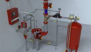
포소 화설비는 일반적으로 수원 (Firewater Tank or Pond), 가압송수장치(Foam Pump), 포방출구 (Foam outlet or Device), 폼저장탱크(Foam Tank), 혼합장치 (Proportioner), 배관 (piping) 등으로 구성된다.


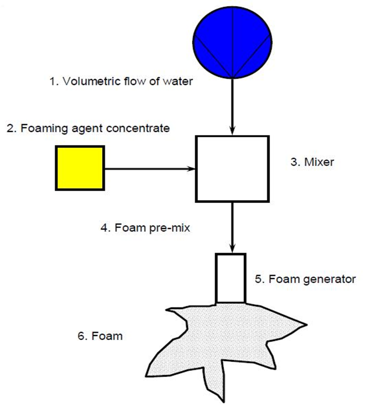
2. 포혼합 개요
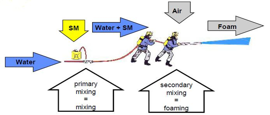
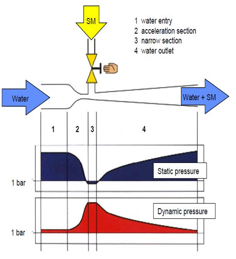
3. 포 혼방 방식의 기본 원리 (벤츄리관)

4. 설치방식에 의한 분류
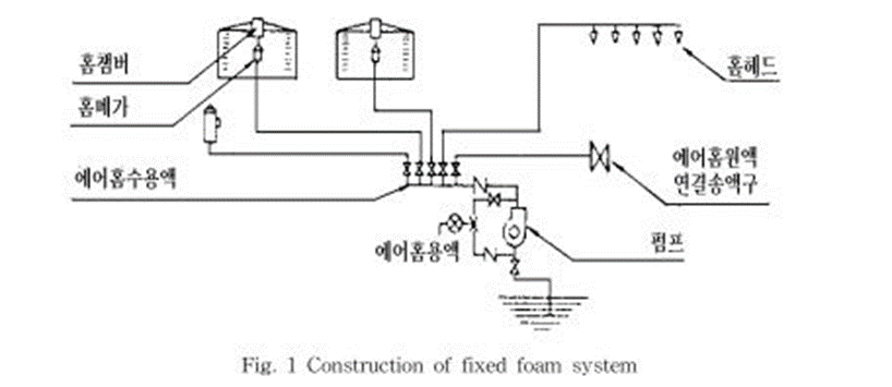
① 고정식 포소화설비 (Fixed Foam system)
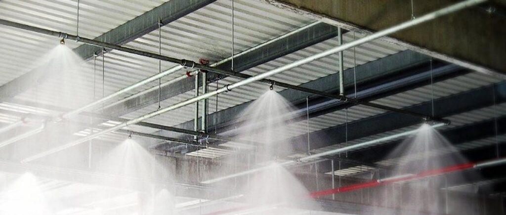
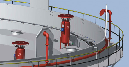
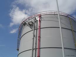
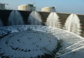
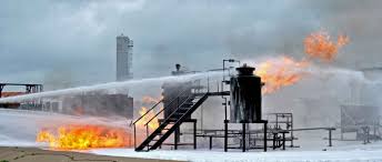
수원, 가압송수장치, 제어밸브, 배관, 포방출구 등의 설비가 고정으로 설치되는 방식으로서 주로 대형소방대상물에 설치하는 방법이다.
NFPA 11 3.3.17.2 Fixed System. A complete installation in which foam is piped from a central foam station, discharging through fixed delivery outlets to the hazard to be protected with permanently installed pumps where required.
② 반고정식 포소화설비 (Semi-fixed Foam system)
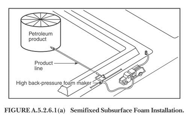
주요 구성부품 중 일부는 고정식으로 일부는 이동식으로 사용하는 방식으로 방호대상물 근처까지는 고정식 배관을 설치하고, 포 수용액을 차량 등으로 현장에 운송하여 배관에 접속하여 포를 방사하는 형식이다.
NFPA 11 3.3.17.5* Semifixed System. A system in which the hazard is equipped with fixed discharge outlets connected to piping that terminates at a safe distance.
NFPA A.3.3.17.5 Semifixed System. The fixed piping installation might or might not include a foam maker. Necessary foam-producing materials are transported to the scene after the fire starts and are connected to the piping.

③ 이동식 포소화설비 (Mobile Foam System)
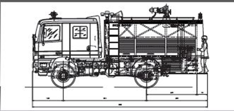
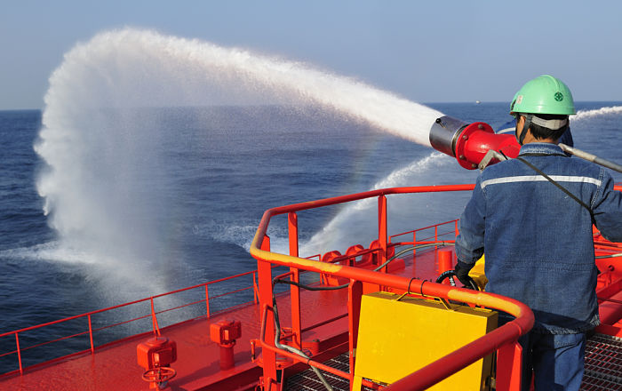
저발포에 의하여 호스접결구 까지는 고정되어 있지만 호스와 노즐을 이동할 수 있는 설비와 포 방생장치 등이 이동할 수 있는 차량에 탑재되거나 차량에 의해 견인되어 사용되는 방식을 말한다.
NFPA 11 3.3.17.3* Mobile System. Any type of foam-producing unit that is mounted on wheels and that is self-propelled or towed by a vehicle and can be connected to a water supply or can utilize a premixed foam solution.


④ 간이식 포소화설비 (Potable Foam System)
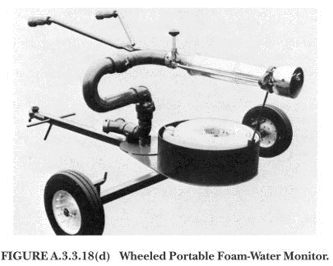
휴대용 간이 포설비와 같은 것으로서 포발생장치, 포수용액, 포방사장치 등을 사람이 이동하면서 사용할 수 있는 방식이다.
NFPA 11 3.3.17.4 Portable System. Foam-producing equipment, materials, hose, and so forth that are transported by hand.



5. 포소화약제 혼합방식에 의한 분류
① 펌프 프로포셔너 (Pump Proportioner, around-the-pump proportioner)
이 방식은 펌프의 토출관과 흡입관을 연결하는 바이패스배관, 흡입기 및 포소화약제의 농도조절밸브로 구성되어 있으며, 바이패스배관의 중간에 흡입기를 설치하여 펌프 토출구의 일부를 흡입기로 보내고 농도조절밸브로 흡입량을 조절한 다음 약제탱크로부터 펌프의 포소화약제를 압송하여 규정농도의 수용액으로 조정하고 송액관을 통하여 발포기에 보내어 공기를 흡입하여 포를 발생시키는 구조이다.

NFPA 11 3.3.25* Pump Proportioner (Around-the-Pump Proportioner). A system that uses a venturi eductor installed in a bypass line between the discharge and suction side of a water pump and suitable variable or fixed orifices to induct foam concentrate from a tank or container into the pump suction line.
NFPA 11 A.3.3.25 Pump Proportioner (Around-the-Pump Proportioner). This device consists of an eductor installed in a bypass line between the discharge and suction of a water pump. A small portion of the discharge of the pump flows through this eductor and draws the required quantity of air foam con-centrate from a container, delivering the mixture to the pump suction. Variable capacity can be secured by the use of a manually controlled multiported metering valve. [See Figure A.5.2.6.1(a).]

A pump proportioner has the following limitations:
- The pressure on the water suction line at the pump must be essentially zero gauge pressure or must be on the vacuum side. A small positive pressure at the pump suction can cause a reduction in the quantity of concentrate educted or cause the flow of water back through the eductor into the concentrate container. (See Figure A.3.3.25.)
- The elevation of the bottom of the concentrate container should not be more than 6 ft (1.8 m) below the proportioner. (See Figure A.3.3.25.)
- The bypass stream to the proportioner uses from 38L/min to 151L/min (10 gpm to 40 gpm) of water depending on the size of the device and on the pump discharge pressure. This factor must be recognized in determining the net delivery of the water pump.


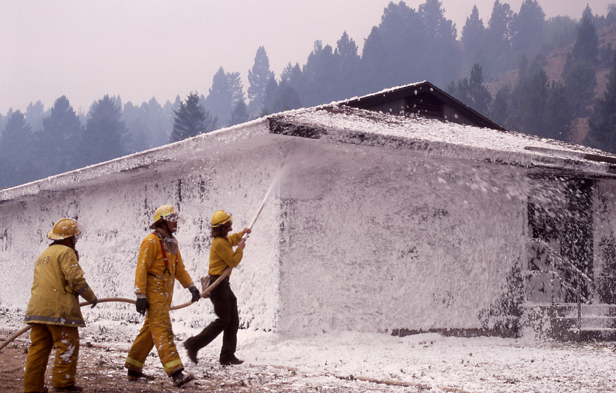
② 프레져 프로포셔너
펌프와 발포기의 중간에 설치된 벤츄리관의 벤츄리 작용과 펌프가 압수의 포소화약제 저장탱크에 대한 압력에 의하여 포소화약제를 흡입, 혼합하는 방식으로 약제탱크 내부에 약제와 물을 분리하는 다이아프레임 또는 레버벽을 격납한 압송식과 다이아프레임이 없는 압입식이 있다.

NFPA 11 3.3.27.1 Balanced Pressure Bladder Tank. A foam concentrate tank fitted with an internal bladder that uses water flow through a modified venturi-type proportioner to control the foam concentrate injection rate by displacing the foam concentrate within the bladder with water outside the bladder.
NFPA 11 3.3.27.2* Pressure Proportioning Tank. A foam concentrate tank with no bladder that uses waterflow through an orifice to displace the foam concentrate in the tank with water to add foam concentrate through an orifice into a water line at a specified rate. This device is only suitable for foams having a specific gravity of at least 1.15.
NFPA 11 A.3.3.27.2 Pressure Proportioning Tank. This method employs water pressure as the source of power. With this device, the water supply pressurizes the foam concentrate storage tank. At the same time, water flowing through an adjacent venturi or orifice creates a pressure differential. The low-pressure area of the venturi is connected to the foam concentrate tank, so that the difference between the water supply pressure and this low-pressure area forces the foam concentrate through a metering orifice and into the venturi. Also, the differential across the venturi varies in proportion to the flow, so one venture will proportion properly over a wide flow range. The pressure drop through this unit is relatively low. [See Figure A.3.3.27.2(a).]

- Foam concentrates with specific gravities similar to water can create a problem when mixed.
- The capacity of these proportioners can be varied from approximately 50 percent to 200 percent of their rated capacity.
- The pressure drop across the proportioner ranges from 34 kPa to 207 kPa (5 psi to 30 psi), depending on the volume of water flowing within the capacity limits of item (2).
- When the concentrate is exhausted, the system must be turned off, and the tank drained of water and refilled with foam concentrate.
- Since water enters the tank as the foam concentrate is discharged, the concentrate supply cannot be replenished during operation, as with other methods.
- This system proportions at a significantly reduced percentage at low flow rates and should not be used below minimum design flow rate.
[Diaphragm (bladder) pressure proportioning tank]
A diaphragm (bladder) pressure proportioning tank also uses water pressure as a source of power. This device incorporates all the advantages of the pressure proportioning tank with the added advantage of a collapsible diaphragm that physically separates the foam concentrate from the water supply.
Diaphragm pressure proportioning tanks operate through a similar range of water flows and according to the same principles as pressure proportioning tanks. The added design feature is a reinforced elastomeric diaphragm (bladder) that can be used with all concentrates listed for use with that particular diaphragm (bladder) material. [See Figure A.3.3.27.2(b).]
The proportioner is a modified venturi device with a foam concentrate feed line from the diaphragm tank connected to the low-pressure area of the venturi. Water under pressure passes through the controller, and part of this flow is diverted into the water feed line to the diaphragm tank. This water pressurizes the tank, forcing the diaphragm filled with foam concentrate to slowly collapse. This forces the foam concentrate out through the foam concentrate feed line and into the low-pressure area of the proportioner controller. The concentrate is metered by use of an orifice or metering valve and mixes in the proper proportion with the main water supply, sending the correct foam solution downstream to the foam makers.
The limitations are the same as those listed for the pressure proportioning tank, except that the system can be used for all types of concentrates.

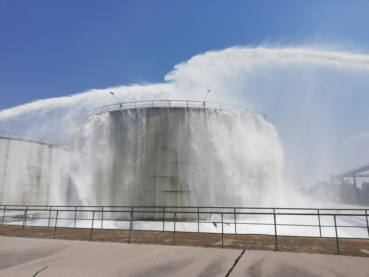

③ 프레져 사이드 프로포셔너
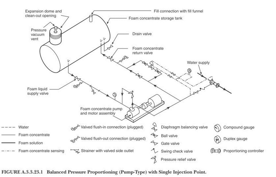
혼합비율을 조절하는 성능을 가진 것으로서 현재 소정의 포혼합농도를 유지할 수 있는 최소의 소요 방사량과 최대의 소요 방사량 범위는 1:5 정도로 설정하는 것이 많다. 그리고 혼합기 내부의 기구가 바뀌는 것에 따라 1:10 정도의 범위를 갖는 것까지도 제작되고 있다 3). 정량혼합장치는 소요 방사량이 일정하게 한정된 구역을 소화할 경우에 사용되는 방식으로 소요유량의 변화에 따라 혼합하는 포소화약제의 양이 변화하지 않는 장치이다.

NFPA 11 3.3.23.1* Balanced Pressure Pump-Type Proportioning. A foam proportioning system that utilizes a foam pump and valve(s) to balance foam and water pressures at a modified venture type proportioner located in the foam solution delivery piping; a foam concentrate metering orifice is fitted in the foam inlet section of the proportioner.
NFPA 11 A.3.3.23.1 Balanced Pressure Pump-Type Proportioning. By means of an auxiliary pump, foam compound is injected into the water stream passing through an inductor. The resulting foam solution is then delivered to a foam maker or playpipe. The proportioner can be inserted into the line at any point between the water source and foam maker or playpipe. (See Figure A.3.3.23.1.) To operate, the main water valve is opened and a reading of the pressure indicated on the duplex gauge is taken. When both gauge hands are set at the same point, the correct amount of foam concentrate is being injected into the water stream. This reading is done automatically by the use of a differential pressure diaphragm valve. Metered proportioning has the following limitations:
- The capacity of the proportioner can be varied from approximately 50 percent to 200 percent of its rated capacity.
- The pressure drop across the proportioner ranges from 34 kPa to 207 kPa (5 psi to 30 psi), depending on the volume of water flowing through the proportioner within the capacity limits of item (1).
- A separate pump is needed to deliver concentrate to the proportioner.


④ 라인프로포셔너
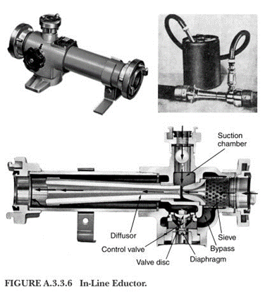
이 방식은 펌프와 포방출구의 중간에 흡입기(벤츄리관의 벤츄리작용)를 설치하여 가압수를 보냄으로써 포소화약제가 가압수에 흡입작용을 하면서 수용액이 형성된 다음 포방출구까지 보내어지는 방식이다.

NFPA 11 3.3.6* Eductor (Inductor). A device that uses the Venturi principle to introduce a proportionate quantity of foam concentrate into a water stream; the pressure at the throat is below atmospheric pressure and will draw in liquid from atmospheric storage.
NFPA 11 3.3.6.1* In-Line Eductor. A Venturi-type proportioning device that meters foam concentrate at a fixed or variable concentration into the water stream at a point between the water source and a nozzle or other discharge device.
NFPA 11 A.3.3.6.1 In-Line Eductor. This eductor is used for installation in a hoseline, usually at some distance from the foam maker or playpipe, as a means of drafting air foam concentrate from a container. (See Figure A.3.3.6 and Figure A.3.3.6.1.) The in-line eductor must be designed for the flow rate of the particular foam maker or playpipe with which it is to be used. The device is very sensitive to downstream pressures and accordingly is designed for use with specified lengths of hose or pipe located between it and the foam maker. The pressure drop across the eductor is approximately one-third of the inlet pressure. The elevation of the bottom of the concentrate container should not be more than 1.8 m (6 ft) below the eductor.
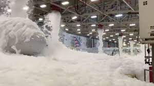
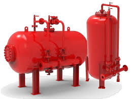
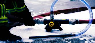


⑤ In-line balanced pressure proportioning
NFPA 11 3.3.23.1.1* In-Line Balanced Pressure Proportioning. A foam proportioning system utilizing a foam concentrate pump or a bladder tank in conjunction with a listed pressure reducing valve. At all design flow rates, the constant foam concentrate pressure is greater than the maximum water pressure at the inlet to the in-line balanced pressure proportioner. A pressure balancing valve integral to the in-line balanced pressure proportioner regulates the foam concentrate pressure to be balanced to incoming water pressure.
NFPA 11 A.3.3.23.1.1 In-Line Balanced Pressure Proportioning. A bladder tank in conjunction with a water pressure–reducing valve upstream of the proportioner can be utilized in place of the foam concentrate pump package. See Figure A.3.3.23.1.1(a) and Figure A.3.3.23.1.1(b).
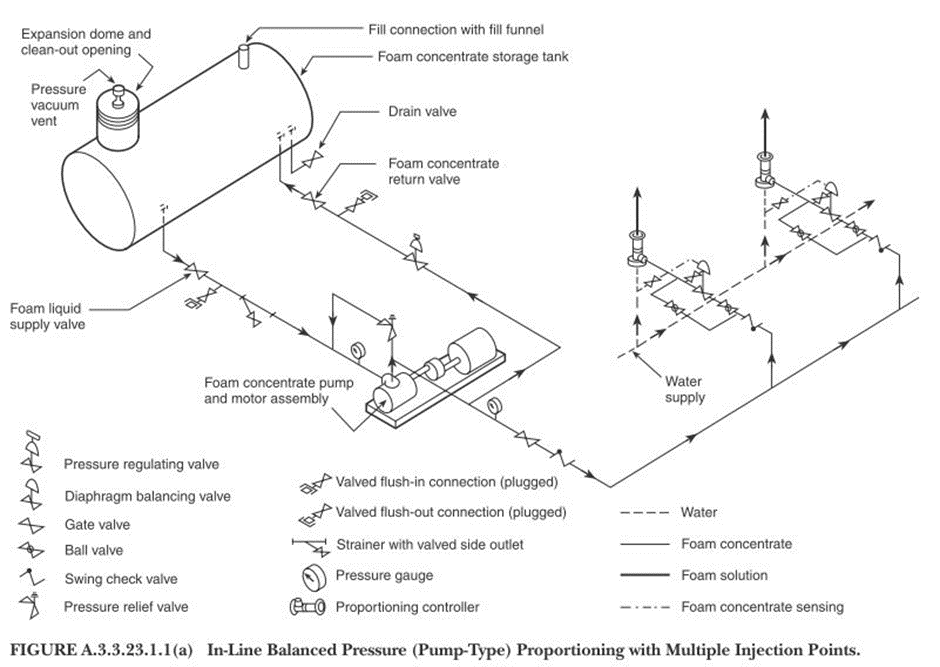




⑥ In-line balanced pressure proportioning
NFPA 11 3.3.23.2* Direct Injection Variable Pump Output Proportioning. A direct injection proportioning system that utilizes flowmeters for foam concentrate and water in conjunction with a variable output foam pump control system.
NFPA 11 A.3.3.23.2 Direct Injection Variable Pump Output Proportioning. Direct injection foam proportioning systems utilize a foam concentrate pump to inject foam concentrate directly into the water stream. Foam proportioning system operation is not affected by water pressure or interrupted while the foam concentrate tank is refilled. Direct injection foam proportioning systems are generally automatic regulation proportioning systems. Automatic flow-sensing direct injection foam proportioning systems utilize an in-line flowmeter(s) to monitor the system operating conditions. System operating data is transmitted to an electronic control, which controls the foam pump output to maintain the desired proportioning ratio. The following two different flow sensing systems are available:
(1) An electronic control receives electronic signals corresponding to the proportioning ratio from the control panel and water flow data from the flowmeter. The electronic control then commands the foam concentrate pump module to deliver foam concentrate at the proportional rate. [See Figure A.3.3.23.2(a).]

(2) An electronic control receives electronic signals corresponding to the foam concentrate flow from a foam concentrate flowmeter, the proportioning ratio from the control panel, and water flow data from the water flowmeter. The electronic control controls the proportioning ratio through a foam concentrate metering valve shown in Figure A.3.3.23.2(b). In a water motorfoam proportioning system, a water motor drives a positive displacement foam concentrate pump. The water motor can be of either a positive displacement type or a turbine type. Water motor foam proportioning systems are automatic regulating proportioning systems. Where a positive displacement water motor drives the foam concentrate pump, the ratio of the water motor displacement to the displacement of the foam concentratepump is the ratio of the desired foam solution. A positive displacement water motor roportioning system re quires no external power. [See Figure A.3.3.23.2(c).]


'소방 이야기 > 포소화설비 (Foam Extinguishing System)' 카테고리의 다른 글
| 포소화설비의 개요 (Foam System) (2) | 2023.09.27 |
|---|---|
| 위험물 저장탱크의 고정포방출구 (Fixed Foam System) (2) | 2023.09.27 |
| 포 소화약제의 종류 (Foam System) (4) | 2023.09.21 |


댓글