
스프링클러시스템의 주요 부품 (Components) In NFPA 13
본 글에서는 스프링클러 시스템(Sprinkler System)의 주요 부품에 대하여 NFPA 13에서 정의하는 내용들을 정리해 보도록 하겠습니다.


General

1) Listing – NFPA 13 sec. 6.1.1
A.6.1.1 Included among items requiring listing are sprinklers, some pipe and some fittings, hangers, alarm devices, valves controlling flow of water to sprinklers, supervisory switches, and electrically operated solenoid valves. Products are typically investigated in accordance with published standards. Examples of standards used to investigate several products installed in sprinkler systems are referenced in Table A.6.1.1. This table does not include a comprehensive list of all product standards used to investigate products installed in sprinkler systems.
6.1.1.3 Equipment as permitted in Table 6.3.1.1 (Pipe) and Table 6.4.1(Fitting) shall not be required to be listed.
6.1.1.5 Components that do not affect system performance such as drain piping, drain valves, and signs shall not be required to be listed.
2) Rated Pressure – NFPA 13 sec. 6.1.3
System components shall be rated for the maximum system working pressure to which they are exposed but shall not be rated at less than 175 psi (12 bar) for components installed above ground and 150 psi (10 bar) for components installed underground.


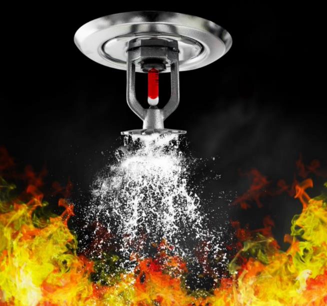
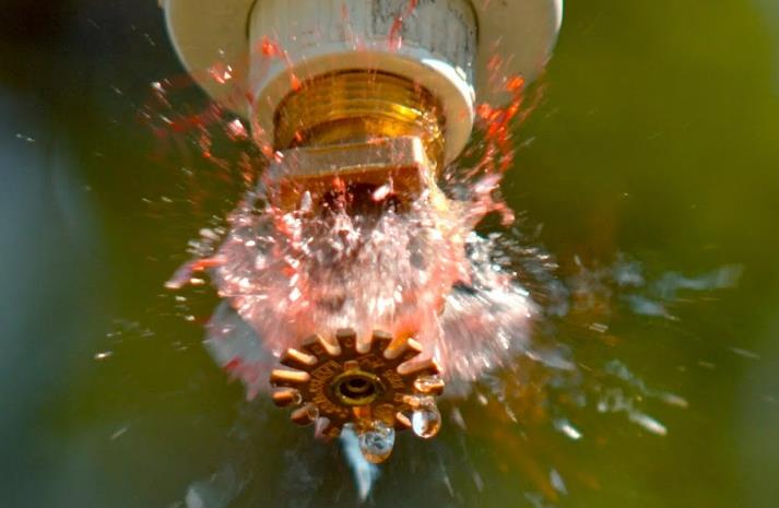
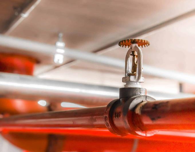
Sprinkler Head
1) Sprinkler Discharge Characteristics– NFPA 13 sec. 6.2.3
6.2.3.1 General.
Unless the requirements of 6.2.3.2, 6.2.3.3, or 6.2.3.4 are met, the K- factor, relative discharge, and marking identification for sprinklers having different K-factors shall be in accordance with Table 6.2.3.1.
6.2.3.2 Pipe Threads.
Listed sprinklers having pipe threads different from those shown in Table 6.2.3.1 shall be permitted.

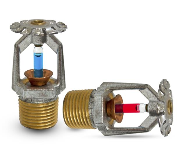
2) Temperature Characteristics – NFPA 13 sec. 6.2.5 / Temperature Rating – NFPA 13 sec. 8.3.2
6.2.5.1 Automatic sprinklers shall have their frame arms, deflector, coating material, or liquid bulb colored in accordance with the requirements of Table 6.2.5.1 or the requirements of 6.2.5.2, 6.2.5.3, 6.2.5.4, or 6.2.5.5.

3) Stock of Spare Sprinklers – NFPA 13 sec. 6.2.9
6.2.9.1 A supply of at least six spare sprinklers shall be maintained on the premises so that any sprinklers that have operated or been damaged in any way can be promptly replaced.
6.2.9.5 The stock of spare sprinklers shall include all types and ratings installed and shall be as follows:
- For protected facilities having under 300 sprinklers — no fewer than six sprinklers
- For protected facilities having 300 to 1000 sprinklers — no fewer than 12 sprinklers
- For protected facilities having over 1000 sprinklers — no fewer than 24 sprinklers


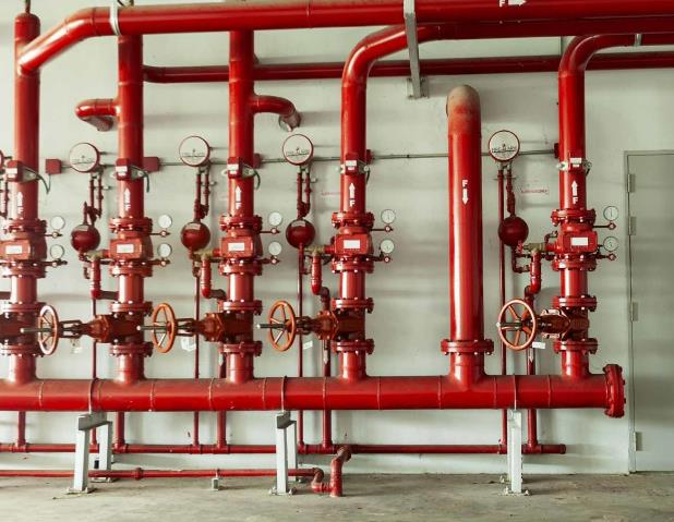
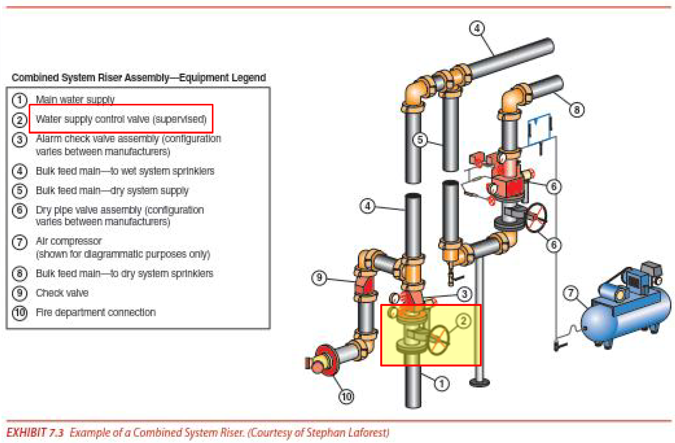
Control Valve
1) Definition – NFPA 13 sec. 3.3.7
3.3.7 Control Valve.
A valve controlling flow to water-based fire protection systems and devices.

[Handbook]
The term control valve clarifies that these valves include gate or butterfly type valves and not automatic system valves such as deluge and pre-action valves, as described in A.3.3.7.
A.3.3.7 Control Valve.
Control valves do not include hose valves, inspector’s test valves, drain valves, trim valves for dry pipe, pre-action and deluge valves, check valves, or relief valves.
[NFPA 15 5.7.1 Control Valves.]
5.7.1.1 All valves controlling connections to water supplies and to supply pipes to water spray nozzles shall be listed indicating valves.
5.7.1.4 Control valves shall not close in less than 5 seconds when operated at maximum possible speed from the fully open position.

2) Valve Closure Time – NFPA 13 sec. 6.6.1.2
Listed indicating valves shall not close in less than 5 seconds when operated at maximum possible speed from the fully open position.
[Handbook]
The minimum valve closure time of 5 seconds reduces the possibility of causing a “water hammer” in a system where water is flowing.
3) Listed Indicating Valves – NFPA 13 sec. 6.6.1.3
Unless the requirements of 6.6.1.3.1, 6.6.1.3.2, or 6.6.1.3.3 are met, all valves controlling connections to water supplies and to supply pipes to sprinklers shall be listed indicating valves.

4) Control Valve – NFPA 13 sec. 8.16.1.1.

8.16.1.1.1.1 Each sprinkler system shall be provided with a listed indicating valve in an accessible location, so located as to control all automatic sources of water supply.
8.16.1.1.1.2 At least one listed indicating valve shall be installed in each source of water supply.
8.16.1.1.1.3 The requirements of 8.16.1.1.1.2 shall not apply to the fire department connection, and there shall be no shutoff valve in the fire department connection.
5) Supervision – NFPA 13 sec. 8.16.1.1.2

8.16.1.1.2.1 Valves on connections to water supplies, sectional control and isolation valves, and other valves in supply pipes to sprinklers and other fixed water-based fire suppression systems shall be supervised by one of the following methods:
(1) Central station, proprietary, or remote station signaling service
(2) Local signaling service that will cause the sounding of an audible signal at a constantly attended point
(3) Valves locked in the correct position
(4) Valves located within fenced enclosures under the control of the owner, sealed in the open position, and inspected weekly as part of an approved procedure
[Handbook]
Central station, proprietary, or remote station supervision methods are preferred over the other methods listed.
The use of electrical supervision has not, however, been mandated due to the cost of such a system, particularly in existing, large, sprawling facilities.


Fire Department Connection
1) Fire Department Connections – NFPA 13 sec. 6.7
6.7.1 Unless the requirements of 6.7.1.1, 6.7.1.2, or 6.7.1.3 are met, the fire department connection(s) shall consist of two 2½ in. (65 mm) connections using NH internal threaded swivel fitting(s) with “2.5–7.5 NH standard thread,” as specified in NFPA 1963.
6.7.1.3 A single-outlet fire department connection shall be acceptable where piped to a 3 in. (80 mm) or smaller riser.
2) Fire Department Connections – NFPA 13 sec. 8.17.2
A.8.17.2 The fire department connection should be located not less than 18 in. (500 mm) and not more than 4 ft.. (1.2 m) above the level of the adjacent grade or access level.
8.17.2.4 Arrangement
8.17.2.4.2 For single systems, the fire department connection shall be installed as follows:
- Wet system — on the system side of system control, check, and alarm valves (see Figure A.8.16.1.1)
- Dry system — between the system control valve and the dry pipe valve
- Pre-action system — between the pre-action valve and the check valve on the system side of the pre-action valve
- Deluge system — on the system side of the deluge valve
8.17.2.4.3 For multiple systems, the fire department connection shall be connected between the supply control valves and the system control valves.


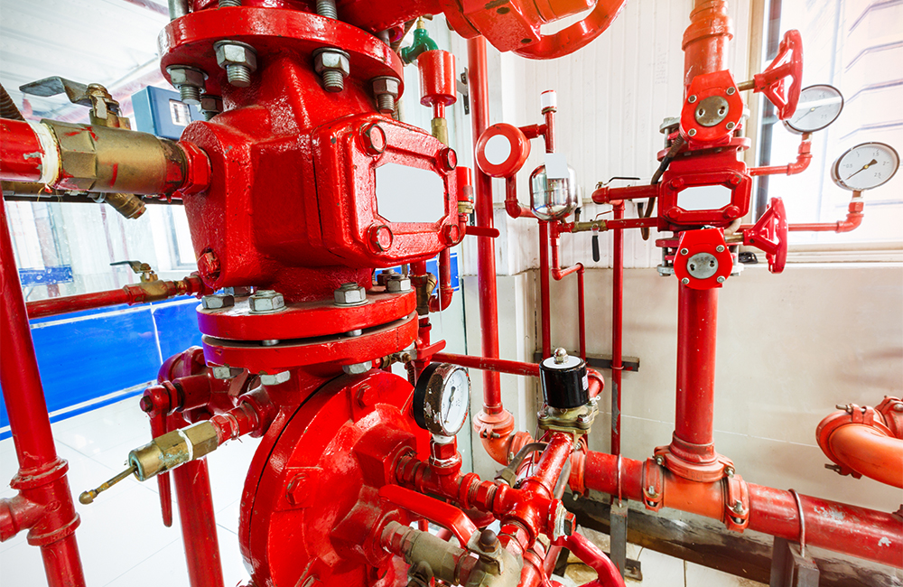
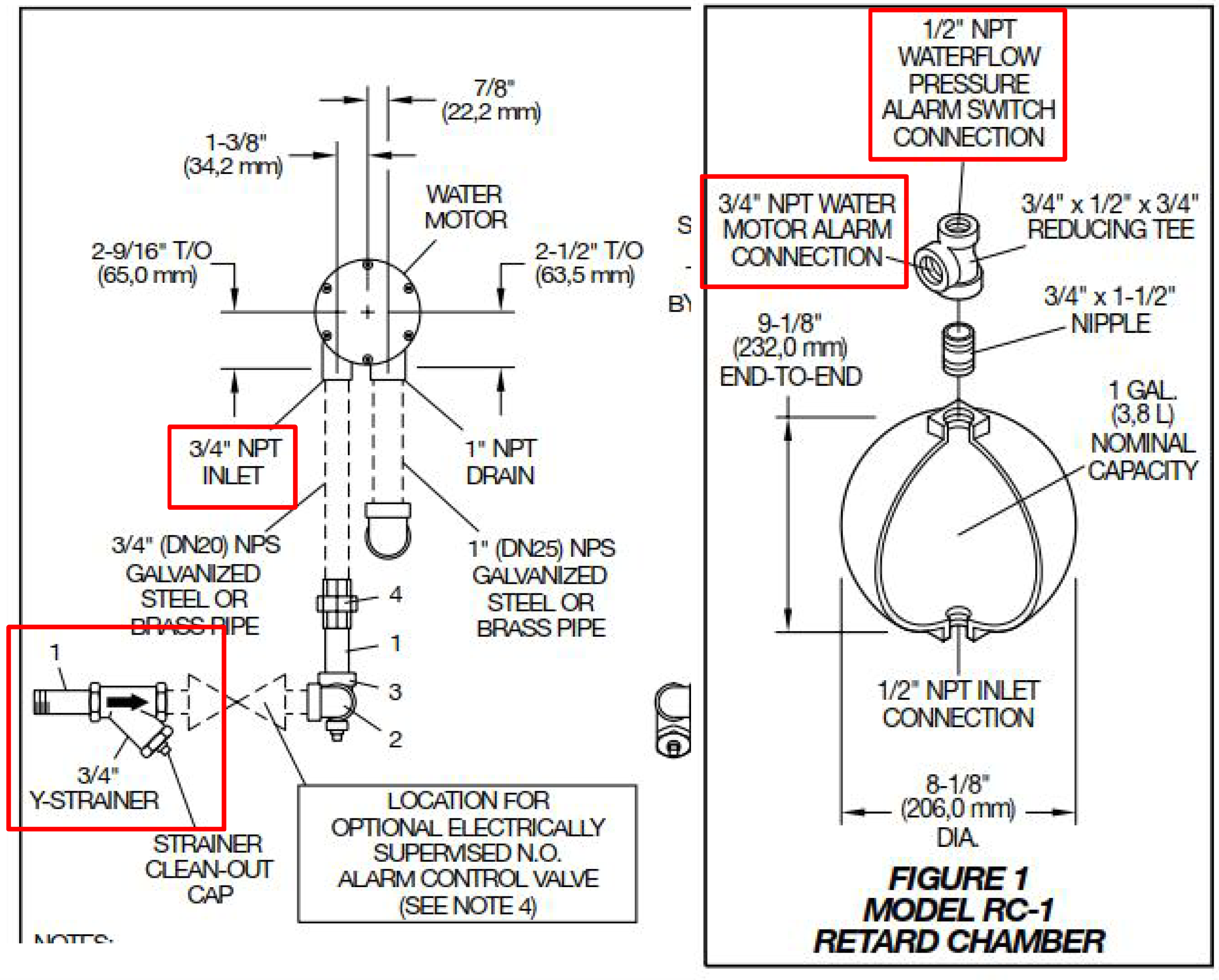
Waterflow Alarm Device (Water Motor Gong)
1) Attachments - General – NFPA 13 sec. 6.8.3
6.8.3.1* An alarm unit shall include a listed mechanical alarm, horn, or siren or a listed electric gong, bell, speaker, horn, or siren.
6.8.3.3 All piping to water motor-operated devices shall be galvanized steel, brass, copper, or other approved metallic corrosion-resistant material of not less than ¾ in. (20 mm) nominal pipe size.
6.8.3.4 Piping between the sprinkler system and a pressure-actuated alarm-initiating device shall be galvanized steel, brass, copper, or other approved metallic corrosion-resistant material of not less than 3⁄8 in. (10 mm) nominal pipe size.
2) Local Waterflow Alarms – NFPA 13 sec. 8.17.1.1
8.17.1.1 Local Waterflow Alarms.
A local waterflow alarm shall be provided on every sprinkler system having more than 20 sprinklers.
8.17.1.5 Attachments — Mechanically Operated.
A.8.17.1.5 Water motor-operated devices should be located as near as practicable to the alarm valve, dry pipe valve, or other waterflow detection device. The total length of the pipe to these devices should not exceed 75 ft. (23 m), nor should the water motor-operated device be located over 20 ft. (6.1 m) above the alarm device or dry pipe valve.
8.17.1.5.1 For all types of sprinkler systems employing water motor-operated alarms, a listed ¾ in. (20 mm) strainer shall be installed at the alarm outlet of the waterflow detecting device.
8.17.1.5.2 Where a retarding chamber is used in connection with an alarm valve, the strainer shall be located at the outlet of the retarding chamber unless the retarding chamber is provided with an approved integral strainer in its outlet.
'소방 이야기 > 스프링클러 (Sprinkler System)' 카테고리의 다른 글
| 일제살수식 스프링클러설비 (Deluge Valve System, Sprinkler System) (2) | 2023.06.23 |
|---|---|
| 준비작동식 스프링클러 설비(Pre-Action System, Sprinkler System) (3) | 2023.06.19 |
| 건식 스프링클러설비(Dry Pipe System, Sprinkler System) (2) | 2023.06.19 |
| 습식 스프링클러설비(Wet Pipe System, Sprinkler System) (2) | 2023.06.15 |
| 스프링클러 설비의 개요 및 분류 (Fire Sprinkler System) (2) | 2023.06.01 |


댓글